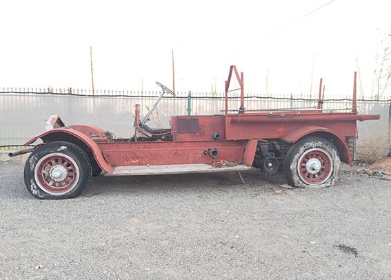
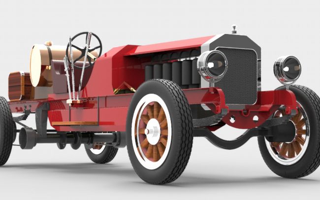
101 years, 1001 miles and a story worth to share….
F6- Seagrave Clutch

The clutch
is of the three-plate dry disc type with the inside face of the flywheel forming one of the plates. The middle disc is faced on both sides with a non-burning fabric. A casting known as the “spring magazine” forms the third plate, and on the opposite side has recesses for retaining twenty springs. The spring magazine is held to the cover plate by four bolts, and when the cover plate is placed in position, it forms part of the flywheel.
By referring to the illustrations and following the description, the operation of the clutch will be readily understood. Four levers equally spaced are pivoted in the “spring magazine” by pins marked “B” and in turn pull upon the four bolts which hold the levers to the cover plate. By this arrangement, all parts that would be difficult to assemble are held as a unit in the cover plate and can be slipped into position without difficulty. The distance that the springs in the magazine can expand is limited by the levers bottoming against the “spring magazine” at the point marked “C.”
When the clutch is “in” and properly adjusted, the spring pressure is exerted between the magazine and the cover plate compressing the middle disc between the magazine and the inside face of the flywheel. At this time, there is no strain upon the levers, nor the fulcrum bolts “D.” So by pulling backward on the clutch pedal to take up any lost motion in the linkage and to remove the weight of the pedal from the clutch shifter collar, it should be possible to move the four bolts which extend thru the cover plate, with the fingers; that there should be some lost motion, approximately 1-64 of an inch, between the faces of the nuts and the cover plate.
As the fabric upon the middle disc becomes worn, the spring magazine will naturally sink deeper, and in so doing, pulls the levers deeper into the flywheel, until the levers bottom on the magazine at the point marked “C,” which has been referred to before. This would take up all the lost motion in the fulcrum bolts marked “D.” The spring pressure would then be carried by the levers and could not be applied to the friction surfaces, which, in turn, would cause the clutch to slip badly.

Adjustment of the Clutch
To correct this trouble, back off the four nuts on the fulcrum bolts until lost motion can be detected (when the clutch “in” By making this adjustment, transfers the spring pressure from the levers to the friction surfaces, allowing greater travel of the springs. In making this adjustment, no more than 1/64 of an inch should be left between the face of the nut and the cover plate, because this lost motion will be compounded and transferred to the ends of the levers bearing against the clutch and shifter collar “E.” which, in turn, will reduce the effective travel of the clutch pedal.
To show an exaggerated case, these nuts were backed off sufficient distance, the levers would be free to move between the points marked “F” and “G,” when the clutch pedal was pushed out, without compressing the springs at all; consequently the clutch would still be “in.”
The adjusting of the four nuts to compensate for the wear of the friction fabric the only adjustment required, and should not be necessary to make this excepting at rare intervals.
Be sure that the same clearance left under each nut, otherwise the “spring magazine” will work at an angle, causing the clutch to drag. This important.
Care of the Clutch
The middle disc the floating member of the clutch, being free to float upon the bearings attached to the pilot on the crank shaft. There scarcely any load upon these bearings. but two are used in – order to hold the disc in perfect alignment. When the clutch assembled, these bearings are packed in grease, and as they are required to work momentarily, in starting and stopping. no means for lubricating has been provided. (On later clutches, a self-lubri cating bearing is used.) Inasmuch as there is no way for the original grease to escape, it should last for years. The only lubri cation required is through the one grease cup shown on the clutch hub which assists the clutch shifter collar in sliding freely thru the cover plate.
The spring magazine has been designed to hold twenty springs, but the full number is not necessary upon small-sized engines. This design, however, permits of the same clutch being used upon differ ent H.P. engines by varying the number of springs and assures the same smooth action on all.